Today was the day to finally climb the tower to remove an old TV antenna, reposition an amateur radio antenna, and install two new antennas, one for OTA TV and the other for a cellular booster system. But there were other things to do before I was ready to climb.
I was up at 7 AM and on my way to Lowe’s in Howell by 7:20 AM in search of a solution to the problem of how to mount the outdoor cellular booster antenna. I ended up buying two 2-1/2 inch U-bolts. Although the tower legs are 1-5/8″ in diameter the angle bracket attached to the bottom of the antenna is 2-1/4 inches wide. Thus I needed the 2-1/2 inch spacing for the threaded ends of the U-bolt to clear the bracket.
Back at the house Linda was up and had the coffee made. We had a quick breakfast of homemade granola. I removed the tire pressure sensors and GPS from my car and headed to Brighton Honda to drop it off for its 100,000 mile service appointment. Linda arrived at the dealership about 10 minutes later. We then headed to Adams Electronics in Wixom. While Adams Electronics primarily serves the public and business communications markets owner Scott Adams, AC8IL, is a long-time ham and a member of the South Lyon Area Amateur Radio Club and Novi Amateur Radio Club. Well known in the local amateur radio community, Scotty is the local go-to guy for certain kinds of equipment. I ordered two coaxial cables from him the other day and we were here to pick them up.
We left to return home at 10 AM so I called Mike (W8XH) to let him know we were running a little behind. So was he, but thought he could be at our house by 11 AM. That gave me time to drill a hole in each of the two U-bolt retaining plates and cut a short piece of 1″ square aluminum tube to use as a spacer. That was the last fabricating I needed to do and we got busy staging all of the materials we were going to need to get the tower work done efficiently.
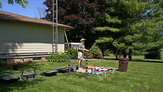
Mike (W8XH) setting up the tools and parts outside the “drop zone” of the 40-foot tower on the east end of the house. (Photo by Linda)
Linda set out a sheet near the tower but not in the “drop zone.” We spread out materials and tools on the sheet and used it to make sure we could find things quickly and keep them from getting lost in the grass. I also brought all of my tool boxes to the tower area. With everything assembled it was time to climb. I set up our 7 foot step ladder on the east end of our rear deck to provide access to the roof near the tower. Mike helped me into his climbing harness and got it adjusted. Once on the roof I took the harness off temporarily as my first task was to remove the 2m/70cm base station antenna. After clipping the plastic cable ties I lowered it down to Mike while Linda took photographs. (She helped with many aspects of the work today but was the only photographer.)
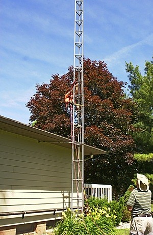
Starting up the tower from the roof of the house. (Photo by Linda)
I put the harness back on and Mike tossed me one of the 100 foot ropes which would eventually be used to haul materials and tools up and down the tower. I secured the haul rope to one of the unused seat clip rings and Mike instructed me on how to secure the harness while climbing. I put the waist strap around the tower and clipped it in. I then put one of the two fall cables, attached to the ring at my upper back, around one of the legs above one of the cross bars above my head and clipped it into the ring at my chest. The tower is adjacent to the east end of the house and is attached to it by two pipe assemblies just below the soffit (the house has hip roofs) so it was easy to step onto it. After that things got tougher.
The horizontal trussing on the tower is two feet apart vertically. That spacing was right at the limit of how high I could lift my right foot and required me to pull myself up part way until I could push with my right leg. Once up on the next rung I attached the other fall cable, moved the first one higher, and slide the waist strap up to position myself for the next step. I repeated this pattern with the two fall cables and the waist strap as I worked my way slowly up the tower, clipping old plastic cable (zip) ties as I went. The tower definitely had some give but I was quickly acclimated to the amount of sway and found it to be acceptable so we decided not to guy the tower with the other three ropes, which would have slowed my ascent even more.
When I finally reached the top of the tower I untied the haul rope, looped it over one of the southeast facing horizontal bars and hauled it up allowing the free end to lower down to the ground. Mike then tied the rope to the standoff pulley I had fabricated and hauled it up to me. I already had cable ties, a diagonal cutter, and a pair of slip pliers with me. I set the threaded rod on the northeast and southeast cross bars, inside and against the two legs that were parallel to the side of the house, and secured it with cable ties. This was a three-handed job that I had to do with two hands but I got it done while only dropping one cable tie. With the pulley rod secured I undid the rope and then undid the knot tying the two loose ends together. I fed one end through the pulley and retied it to the other end. We now had a way to haul materials and tools (in a bucket) up to me at any needed height while keeping it 18 inches away from the tower.
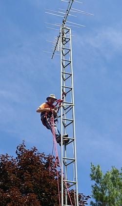
Three-quarters of the way up ad working with the haul rope. (Photo by Linda)
The next task at the top of the tower was to remove the old TV antenna, mast, and rotor. When I finally had a close up view of these old components it became apparent that my best course of action was to try and unclamp the base of the mast from the rotator, lift it off of the rotator, and toss it to the ground.
The mast clamp parts were all very rusty so Linda got the WD-40 and Mike sent it up in the bucket. I sprayed the nuts on the mast mounts and also the rotator leg clamps. I tried undoing the mast clamps with a slip pliers but it was no good, so Mike sent up three open/closed end wrenches. One of them was the right size and to my surprise the rusted nuts broke loose and started backing off. One of them did not want to come off but unscrewed the entire bolt instead. Fine. The bolt had a screwdriver slot in the top and was threaded into the rotor housing and I did not care how it came out as long as it did. I got the mast clamps loose enough that I could work the bottom of the mast free from the top of the rotor. There was a lot of rust there too. After clipping some coax cables, rotor control wires, and plastic cable clamps I repositioned myself up one rung on the tower so I could get enough leverage to the lift the mast clear of the rotator collar and control it well enough to make sure the antenna fell to the ENE away from the house and my helpers down below. And that is exactly what happened.
The first antenna to get mounted was the outdoor antenna for the cellular booster system. Mike sent the antenna up in the bucket along with the various pieces I needed to secure it to the short top/center mast support tube so the entire antenna, which is omnidirectional, was above all parts of the tower. What would have been an awkward assembly on the ground took on added difficulty 40 feet in the air but I got it secured with good access to the N-female connector on the bottom.
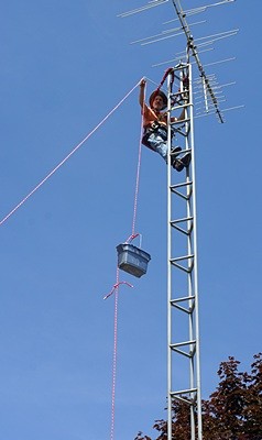
At the top with the pulley in place and using it to haul up a bucket with tools and parts. Mike is controlling the haul rope on the ground. (Photo by Linda)
We decided to run the coax on the outside of one of the tower legs rather than down the inside of the tower. Mike tied the LMR-400 coax to the rope and hauled it up to me. In addition to the haul rope Mike tied a second control line to the bucket to keep it from swinging all over the place. I connected the coax to the antenna feed point and then wrapped the connection with coax seal tape. I then routed the coax down the east leg of the tower and zip tied it to take the weight off of the antenna connection.
Next up was the 2m/70cm amateur radio base station antenna, often referred to as a 2m/440 dual band antenna. (In this nomenclature the “2m” refers to a range of wavelengths for one of the VHF ham bands and the “440” refers to a range of frequencies for one of the UHF ham radio bands, so it is a mixed units designation.). The antenna is about five feet long with three short counterpoise (ground plane) rods near the base. It had an LMR-400 style cable connected to it but with PL-259 male connectors on each end. The antenna feed point is an N-female connector so I had an adapter installed to make everything compatible. Mike removed the coax and the adapter, zip tied the antenna to the haul cable at three points, put the 10mm wrench in the bucket, and hauled it up to me.
The ham radio antenna was also tricky to get mounted. I installed it at the top of the northwest leg so that most of the antenna was above the tower and two of the three short counterpoise were parallel to the west (N-S) and northeast (NW-SE) crossbars. The antenna by itself is light in weight but it is five feet long and mounts at the bottom nine inches, so most if it was above me with a tendency to wave around in mid-air. With the coax connected, however, it weighed quite a bit more. I temporarily zip tied the coax to take the weight. I then had to hold the antenna with its base against the northwest post at my head level, push a U-bolt through the mounting bracket and past the tower leg, slip the mating clamp over the two ends of the U-bolt, and then get a small lock washer and nut on each threaded bolt end. I then had to repeat this for the second U-bolt. Again, a three-handed job that I had to do with only two hands.
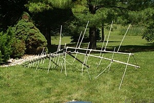
The old OTA TV antenna and mast on the ground. It came down by the gravity method. (Photo by Linda)
The bonus to this work at the top of the tower was a commanding view of the surrounding countryside, which was mostly trees in every direction. I even saw two towers far to the north and was kept company by a soaring vulture just to the NNE. I was also able to determine that the tops of the large white pine trees behind the east end of our house are about 10 feet higher than the top of our tower, putting their overall height at about 55 feet as their bases are lower than the base of the tower. We plan to put the 70 foot tower at a spot that is surrounded by these trees on three sides (W, S, and E) so the top of the tower, and any antennas mounted there, will be well above the tree tops. That is especially important as we plan to eventually put an HF beam antenna up there on a mast attached to a rotator and it will need to be able to rotate freely for 360 degrees.
The final antenna was the hardest. The Antennas Direct DB8e OTA UHF/digital TV antenna was very large and heavy by comparison to the other two. In this case ‘heavy’ meant a few pounds. It is actually two UHF antennas mounted at the end of a dual support arm structure. The support arm mounts to a vertical pole, such as a tower leg, at its midpoint and there is a combiner box located there as part of the mount. A short length of RG-59 (75 ohm) coax connects each antenna to the combiner box and the main coax connects there as well.
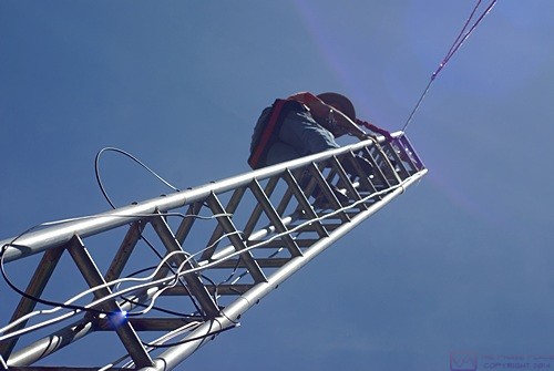
How tall the tower appears (and feels) depends on where you are standing. Pulley and haul rope in the upper right. Lots of coaxial cables to be dressed (secured) on the way down. (Photo by Linda)
RG-59 is a different kind of coaxial cable from the LMR-400 used for the first two antennas. LMR-400 has a 50 ohm characteristic impedance and is used for receiving and transmitting RF energy with considerable power if needed. RG-59 is much smaller in diameter, more flexible, has a 75 ohm characteristic impedance, and uses F-connectors that are the standard for OTA TV, video, and satellite cables. But I have gotten ahead of myself. I had to come down a few feet on the tower to install the TV antenna but before doing that I had to start securing the transmission lines to the tower legs with cable ties.
Mike rigged up the haul rope in a ‘Y’ to lift the antenna from its center of gravity while actually attaching the rope to its ends. That allowed the haul rope to both support the weight of the antenna and keep it oriented correctly while I positioned and clamped it to the southwest tower leg with the dual support arms pointing in an east-west direction. Because of where I had the pulley mounted, and the length of the ‘Y’ in the support rope, I had to mount the antenna a few feet lower on the tower. Fortunately the slightly lower height was not going to affect its performance.
Like the ham radio antenna, the OTA TV antenna mounted to the tower leg at two points. The upper assembly was a U-bolt with a retaining bracket on the back side. The lower assembly was a pair of straight bolts that went through the combiner box past the tower leg and had a retaining bracket on the back side. The antenna came with wing nuts instead of washers and regular nuts, which helped a little, but I really needed three hands to get the antenna into position and tighten the mounting brackets.
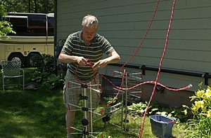
Mike ties off the DB8e OTA TV antenna with an inverted “Y” so it will haul up in the proper orientation. (Photo by Linda)
Once I had the antenna sufficiently attached to the tower I was able to position the support arm close to the southeast facing side of the tower. I then pointed the antenna on the east end of the arm ESE towards the Detroit area TV towers and tightened the two nuts on the mounting studs. (The horizontal dual support arms are about 3 feet long so I was able to reach through the tower to get to the mounting studs and nuts.) I left the antenna on the west end of the support beam loose and turned it out of my way so I could complete other tasks.
Mike attached the end of the main RG-59 coax to the haul rope, put the amplifier and a 2-foot length of RG-59 coax in the bucket along with lots of zip ties, and pulled them up to me. The amplifier is about 3″ wide by 2″ high and 1.5″ thick including the concave plastic backplate. The backplate accepts two zip ties for mounting to a pole. I positioned the amplifier about 8 inches below the antenna combiner box and cinched up the two zip ties. I then connected the short coax to the combiner box output and put the combiner back it its protective, weather-gasketed plastic box. I connected the other end of the short coax to the amplifier input and wrapped the connection with coax seal weatherproofing tape.
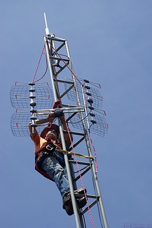
Installing the DB8e OTA TV antenna required three hands. Note that I am installing it at the highest point possible when it is suspended from the pulley with the haul rope in an inverted “Y” attachment. The yellow waist strap allowed me to lean back and work while the two red security straps would catch me if something broke. (Photo by Linda)
I attached the main RG-59 coax to the output of the amplifier, which is also the DC power input, and wrapped the connection in coax weather seal tape. I then dressed the cable and secured it to the tower leg. I aimed the antenna on the west end of the support arm WNW towards the East Lansing TV towers and tightened the nuts to lock it in position.
At this point I was finally done working on the antennas but had three coaxial transmission line running down the outside of the tower, one by each leg. As I descended the tower, reversing the protocol I used going up, I secured all three cables every few feet. I finally had my feet back on the roof at 2:20 PM, almost exactly 2 hours and 30 minutes from when I started climbing. Projects usually take me twice as long as I think they will but this was about half as long as I thought it would take, so we were all pleased that the work had gone smoothly and relatively quickly. My main objective was to get the old TV antenna down and the three antennas up but my secondary objective was to only climb and descend the tower once. Mission accomplished, at least for now.
By now we were all hungry and thirsty so Linda made chickpea salad sandwiches and set out fresh sweet peppers, sliced apples, baby carrots, and cold water. After a suitable lunch break we returned to the next phase of the work which was routing the coax cables into the cable entry box (CEB) and making the connections.
We started with the RG-59 coax from the OTA TV antenna. I coiled the extra cable and hung it on the tower (with zip ties, of course), routed it into the CEB and connected it to the power inserter / lightning arrestor. We purchased this cable from a Radio Shack store in Florida two winters ago to hook up our bus to the RV resort cable TV system. Besides the coax it had a separate ground wire. The amplifier and the power inserter both had connections for a separate ground wire so I connected it on both ends.
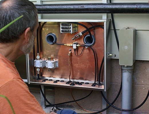
Routing coaxial cable into the cable entry box from the tower and the basement and making the connections. (Photo by Linda)
We had already routed a 75 ohm video cable from our bedroom TV to the sump pump room in the basement. I selected a suitable length of this same type of cable from our existing inventory, connected it to the other side of the power inserter, and routed it through the back of the CEB into the sump pump room where Linda guided it. Conveniently, I had a double-ended F-female barrel connector designed to connect together two cables with F-male connectors. I plugged in the AC power adapter for the power inserter, which was already in the sump pump room, and we went upstairs to see if we were receiving any TV stations.
We set the ‘Source’ on the TV to ‘Antenna’ and did an ‘Auto Scan’ for digital channels only. There are very few analog TV signals still in use and the ones that are reside in the old VHF TV spectrum which our new antenna cannot even receive. The scan found 58 signals, which obviously included the sub-channels. Besides the main Detroit stations and the East Lansing PBS station we got other Lansing area stations and even a station from Flint. The nice thing about digital TV is that if you get a picture at all it is very good.
There is a large TV tower at I-96 and US-127 on the southeast corner of Lansing so we were probably picking it up. There are several TV towers SSW of Lansing about 35 miles that serve Battle Creek and may serve Lansing and Kalamazoo. They are 50+ miles from us and I did not have the west antenna pointed in exactly that direction but it may have been close enough to pick them up. Flint is at least 35 miles away straight north off the sides of both antennas so theoretically we should not have received any stations from that direction. We will have to check the AntennaPoint.com website and confirm by station identifier what stations we are actually receiving.
Feeling good about our success so far we routed the coax for the cellular booster across one of the support arms that brace the tower to the house just under the east soffit. We dropped it down next to the wall and brought it into the bottom of the CEB, replacing the hole plug with a rubber grommet. Routing it this way kept it out of the way of future foot traffic, or lawn and garden work, in the space around/between the tower and the CEB. I connected the cable to the lightning arrestor and coaxed it unto position inside the CEB. LMR-400 is stiff and bending it sharply will damage it.
I connected one end of the 15-foot LMR-400 cable to the other side of the antenna arrestor and routed it into the sump pump room where Linda guided it into position. I secured it to the ceiling, brought it down the opposite wall, put a large 180 degree bend in it, and attached it to the connector on the bottom of the cellular booster. I turned it on and watched the lights blink for a while. All three of us then started checking signal strength throughout both floors of the house. All five of the ‘Alert’ lights went from blinking yellow, which means the unit is adjusting the gain on that band, to solid yellow, which is not described in the manual. Since we had not yet registered the device with Verizon Wireless I turned off the booster.
Back out at the CEB I removed one of the hole plugs directly below the input of the Morgan VHF lightning arrestor. We routed the coax for the 2m/440 ham antenna across the tower brace, down the wall, and around through the bottom of the box where I attached it to the lightning arrestor input. I had an old piece of 50 ohm coax with an N-male connector on one end and a PL-259 (male) connector on the other end. I attached the N-connector to the output of the VHF lightning arrestor and fed the other end through one of the 2″ conduits into the sump pump room where Linda routed it out into the ham shack.
We set our “Go Box” on the desk, plugged the PL-259 into the SO-239 socket on the back of the case, plugged it in to AC power, turned on the power supply, and turned on the radio. The radio, an Icom IC-7000, came up tuned to the South Lyon (K8VJ) repeater. I transmitted and successfully triggered the repeater, which is currently at a secondary site about 20 miles from our tower. Mike went out to his car and used his mobile radio to verify that we could transmit to and receive from the repeater. I had a lot of background static (white noise) so Mike switched modes and transmitted directly to our antenna. The signal was full scale and full quieting. I have a ground lug in the Go Box but did not have it connected. I vaguely recalled that I had to ground the box at the previous house to eliminate a noise issue. (The radio and power supply are grounded to the box.)
I switched the radio to UHF and it was set for the Novi repeater. I listened but did not hear anyone transmitting so I transmitted, giving my call sign and a brief message, and then listened. I did not get a reply even though Mike was also monitoring the Novi repeater so I switched back to the South Lyon repeater. Mike indicated that I had, indeed, triggered the repeater and that a couple of other hams acknowledged hearing me in addition to him. It thus appeared that I did not have something set up correctly on the receive side of the radio for the Novi repeater but the system (radio, cables, arrestor, antenna) was clearly working.
That was enough work for one day so we gathered up all of the tools and unused materials and put them away. We offered to take Mike to dinner as a ‘Thank You’ for his assistance. It was more than helpful to have someone on the ground who was familiar with tower operations. We considered several dining options but opted for Olga’s in Brighton. Linda and I had small salads, sans the Feta cheese, veggie Olga’s that were excellent, and curly fries without Tabasco sauce for the ketchup. Warning: As inconceivable as it may sound, Olga’s does not have any kind of hot sauce in its restaurants. Mike had a dish with chicken in that he said was very good.
Mike headed home from the restaurant as did we. We were tired but very pleased with what we had accomplished in the course of the day. We celebrated our accomplishments by watching several programs on Detroit PBS, something we have not been able to do for more than two years.
