(Photos of this work are in the gallery post for this date.)
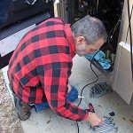
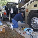
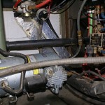
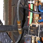
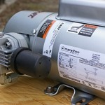
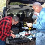
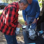
John and Marian returned at 10 AM today. I unpacked all of the tools again, shut off the power to the pressure switch for the auxiliary air compressor, and removed the cover. Sure enough, the diagram was right there. The pressure switch was a Connor designed for air systems. It was not a water well pump control switch although externally you would not know the difference. It was designed to allow adjustment for a cut-in pressure as low as 40 PSI and a cut-out pressure as high as 160 PSI with an adjustable pressure difference between cut-in and cut-out of 20 to 50 PSI. The two large spring-loaded shafts moved the operating range up and down while the smaller single shaft adjusted the differential. It presumably had the two large springs, instead of the usual single one found in a water well switch, because of the higher operating pressures.
After figuring out a combination of tools that allowed me to turn the adjustment nuts, I backed off (CCW) the two nuts on the large spring shafts equal numbers of turns. The adjustment rate appeared to be approximately 3.0 to 3.5 PSI per full revolution. I lowered the cut-in pressure, turned the power back on, and bled the auxiliary air tank until the compressor came on. A little more adjustment and I had the cut-in pressure set to 65 PSI. That put the cut-out pressure at approximately 90 PSI. I decided to raise the cut-off pressure to about 95 PSI, a 30 PSI differential, in order to get a slightly longer off-time. I checked the time with my stopwatch and the compressor was coming on about every 2 hours and running for about 3 minutes. Not bad compared to the 20 – 25 minute cycle we were seeing before the old compressor died. In subsequent tests it has stayed off as long as 2 hours 15 minutes if I did not use any air powered accessories.
The 65 PSI cut-in pressure was selected to keep the overall system pressure above 65 PSI. There is a pressure regulator / water separator that takes air from the auxiliary air manifold and supplies it to the house accessories, specifically the toilet, pocket door, and waste tank dump valves. The toilet, in particular, wants to see 60 PSI to operate properly. The auxiliary air compressor also maintains the pressure in the suspension/brake systems, and I like to keep that pressure above 60 PSI. If not for these minimum pressure requirements I would set the pressure control switch to cycle between 45 and 95 PSI and extend the off-time to 3 or more hours.
With the compressor project wrapped up for now I got out my Pro-Link ECM diagnostic instrument. The ECM for our DD8V92TA is a DDEC II. I turned on the chassis batteries and we plugged the Pro-Link power cord into the 12VDC outlet (cigarette lighter) in the driver’s area and plugged the data cable into the diagnostic port in the outside bay under the driver’s seat. (Note to self: Install a 12VDC outlet next to the data port for future use.) After referring to the manual, we were able to examine the data in the DDEC II.
There was one Inactive code set as follows:
MID: 128 Engine | Fuel Temp Sensor | Input Voltage High | I1 PID: 174 FMI: 3
We did not check for active codes as that required the engine to be running and I don’t like to start unless I am going to run it long enough to bring it up to operating temperature.
This was the same code that Bill and I saw in Arcadia and then cleared, so it must have reappeared on the drive back to Williston on January 1st. I had purchased a new fuel temperature sensor early last year and had our mobile mechanic, Joe Cannarozzi, install it last spring. It is possible, though unlikely, that this new sensor was bad. I also do not think I that the bus has a fuel temperature issue. That leaves wiring or the DDEC II as possible culprits, but not necessarily the only ones. The fuel temp sensor is mounted in a dry pocket on top of the engine underneath the DDEC II. I believe the wires go directly from the sensor through a connector to the computer, so the wires and/or connector are obvious places to look for a problem. More importantly for us today, it appeared that the check engine light has been coming on for a reason, not at random, displaying an active code while driving and coming on and going off as the error condition appeared and disappeared.
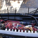
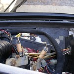
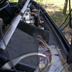
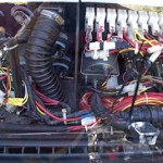
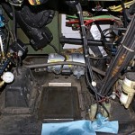
Now for the dashboard. The cover just lifts off, exposing the top and back side of all the gauges, switches, indicator lights, dash lights, rotary controls, and wiring; lots of wiring. The area behind the dashboard is not very deep—12 inches at most—and it is easier to see this area from outside through the driver side lower windshield than from inside and above. Extensive work behind the dashboard would require the removal of the driver side lower windshield.
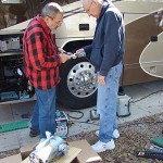
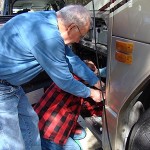
John and Marian studied the wiring through the windshield and spotted some issues. We followed the wires coming out of the back of the speedometer into a large bundle that went to a large circular connector with a twist-latch to hold it together. There are several of these connectors to accommodate all of the dashboard wiring, plus smaller connectors for the dashboard lights and miscellaneous power feeds. (Except for two small air lines for the primary and secondary air system gauges, and some mechanical connections for the front HVAC system, it appears that undoing these wiring connectors would allow the dashboard panels to be removed intact. That would provide an alternate way to work on the wiring.)
The insulation on several of the wires was abraded or had been chewed off. (Mice are known to chew insulation off of wires.) We taped the damaged wires to prevent any further deterioration. We also noticed a wire that came out of the connector that contained the speedometer wires and looped back into the connector. It was approximately 6 inches long and the insulation was missing from one side of the middle four inches, exposing the stranded copper conductor. Not only was that a potential short circuit, the conductor was not in good shape. It was slightly corroded due to atmospheric exposure and it was frayed in several places with only a few strands providing continuity. This in turn would look like a resistance to the circuit, causing a voltage drop and reduced current flow. We clipped out the bad section and spliced in a new piece if wire.
(As a side note, there are only two obvious reasons to loop a wire back through a connector like that: 1) It was intended to go to something that was not installed and then continue on to something else, or 2) It was being used to detect that the cable was plugged in.)
We separated the two halves of the connector and sprayed them with contact cleaner. While they dried we checked for ground connection problems, but did not see any obvious ones. The ground on the speedometer mounting bracket looked sound and all of the other speedometer wires were shielded pairs; the instrument itself did not use chassis ground for its signals.
While we had the dashboard exposed I decided to remove the radar detector. I have never used radar detectors, but it was already installed in the coach when we bought it. I had never used it and did not intend to. It was taking up space and making access to things more difficult. (I had previously removed an electronic compass that did not work and I still need to remove the “musical horn” which we don’t use because it’s annoying.)
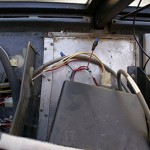
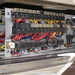
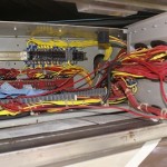
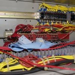
With the dashboard work completed we opened up the electrical service bay above the driver side steer tire. This bay contains a lot of chassis electrical components such as relays, circuit breakers, terminal strips, diodes, and the anti-lock brake computer. What we were looking for, however, was the Speed Limit Switch (SLS).
The SLS is used on seated coaches to disable the kneeling feature of the suspension when the coach is moving. In order to do that, the speedometer wires pass through the SLS enroute to the dashboard gauge. The Prevost national service advisor for conversion shells, Bill Jensen, told me back in January that this switch might be installed in our coach even though it was not used, and that it was a possible point of failure that might cause our intermittent speedometer problem.
The Speed Limit Switch was not present, but there was a DB-15 connector at that location that could have plugged in to it. The connector was plugged in to a mating connector that did not have any wires coming out of it. Looking in the cable access hole on the end we could see wires inside. It was a loop back terminator. We separated the two connectors and sprayed them with contact cleaner but we did not open them to check the integrity of the wiring inside.
We buttoned everything up and called it a day around 2:30 PM. I won’t know if any of the work we did today fixed our speedometer problem until we depart Williston Crossings RV Resort in April.








 So I selected the other one on SW Archer (US-24). We routed ourselves over to FL-121 southbound which intersects Archer close to the Walmart. YOU DO NOT WANT TO BE ON THIS ROAD DURING AFTERNOON RUSH HOUR, which is actually “hope you’re not in a rush” hour. Truthfully, you do not want to be in Gainesville during the evening rush hour. Period. End of story. Total gridlock. Fortunately we were not in a rush to be anywhere in particular by any certain time so we only had to deal with our self-imposed frustration at being stuck in traffic. It won’t happen again, at least not in Gainesville.
