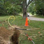
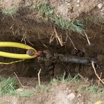
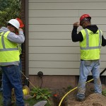
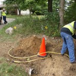
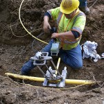
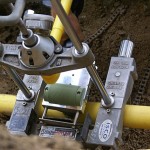
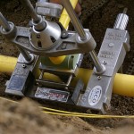
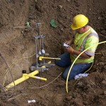
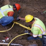
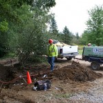
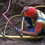
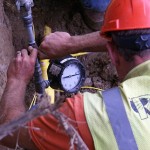
Here is a photo gallery of the major steps involved in running a natural gas pipeline to or neighborhood and connecting up our house. Consumer’s Energy is the utility company involved and Roses Construction was the contractor who did all of the work.
Gallery One – Main Line Directional Drilling
- Pulling 2″ plastic main line back through to directional drilling rig.
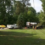
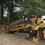
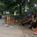
- The directional drillng (horizontal boring) rig set up by our west culvert to drill back to the line at our east culvert.
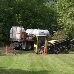
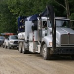
- The directional drilling rig takes water from a tanker truck for its operation.
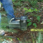
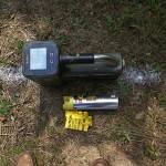
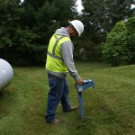
- This portable device senses where the drill head is up to 20′ behind to 20′ in front.
- Larger than the can of spray paint. White paint is proposed location of the gas line, yellow paint is the actual location.
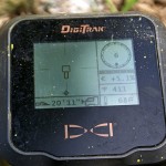
- The sensor operator radios directions to the rig operator. The sensor screen shows the direction and pitch of head travel and predicts where it will end up.
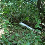
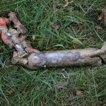
- This is the end of the 2″ main gas line running east from our east driveway culvert.
- The sensor operator trying to get the drill head to emerge near the existing piece of pipe.
- The drill head emerges heading east just east of our east driveway culvert.
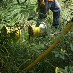
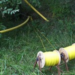
- Two spools of #10 electrical wire being readied to be pulled through wit the 2″ plastic pipe.
- Not sure what the actual name is, but this thing gets pinned through a hole in drill head and the plastic gas line gets attached to it.
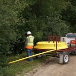
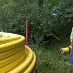
- The 2″ gas main comes in very large spools on a special trailer
- The 2″ plastic main and the two #10 tracer wires unwind from their spools as the drilling rig pulls them back through the shaft it just bored.
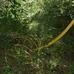
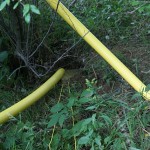
- Gas line (L) and tracer wires being pulled into the bore hole. Previously pulled line (R) sticking out of the ground.
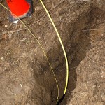
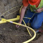
- Any place these lines emerge from underground and criss-cross they will get fused together and buried.
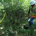
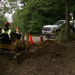
- The contractor tries to minimize property and environmental damage. This truck sucks up (vacuums) the slurry (water/dirt mixture) created when pumping water into the drill hole while drilling.
Gallery Two – The Large Vermeer Horizontal Boring Rig
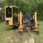
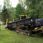
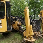
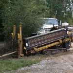
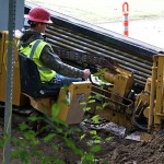
- This was a fascinating machine. The operator sits in the enclosed cab. The two vertical posts contain anchor screws. Drill rods are loaded at an angle on the right.
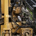
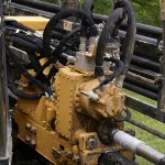
- This hydraulic motor turns the drill rods and slides to bore in or pull back.
- These lengths of rod are removed from the storage bin one at a time, loaded into the rig, and attached to the last rod in line, all by the machine.
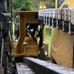
- The back end of the hydraulic motor sled showing the base rail it slides on and the flexible hose chase (upper R).
- Another view of the traveling hydraulic drill motor. Hydraulic pressure is generated by a large diesel engine at the rear of the rig.
- Notice the muddy drill rod (lower right) emerging from the bearing collar between the anchor screw towers.
- This was at the far west end of our property by the court. They dug a big hole each place the line sections had to be fused together and buried.
Gallery 3 – Installing The Branch Line To Our House
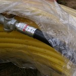
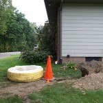
- A large roll of 1″ id plastic gas line that was used to go from the 2′” main line by the street to the SE corner of our house.
- The black line is fused to the end of the yellow line on one end had has a threaded shutoff valve on the other end to connect to the meter.
- Because there is a propane line and pressure regulator at this corner of the house and a buried power line for the bus, they had to trench and hand dig before boring in the branch NG line.
- The small (1/2″) gas line and trace wire for the house across the street. They bored under the road from the other side and pulled the line back in from the corner of our driveway (our house can be seen in the rear).
- By the time the crews drilled and connected the branch lines the 2″ main line had natural gas in it at 60 PSI. Note the presence of the fire extinguisher.
- Our neighbor’s branch line and tracer wire.
- This is the smaller Vermeer directional drilling rig they used to bore the branch lines up to houses when they were not able to trench and plow them i.
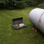
- This instrument was connected to the copper propane line near the tank and to a ground rod. It generates a signal that they can use to locate the buried line.
- This the sensor used to locate the propane line. They hooked it up to the line at both ends but could not locate it.
- This apparatus gets pinned to the end of the drill head and the plastic gas line gets connected to it and pulled through the hole.
- Th small Vermeer drilling rig positioned just to the east of our east driveway culvert and drilling towards the SE corner of our house.
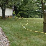
- Here you can see from the drilling rig to the SE corner of our house, about 120 feet.
- The earth here is all dug up because they fused two pieces of 2″ gas main at this location and then buried it. They are not allowed to leave lines exposed
- The operator station on the small Vermeer is not enclosed like the big one.
- The drill head sensor operator (crew chief) monitoring our branch line bore and radioing instructions to the rig operator.
- The roll of 1″ id line was 500 feet long and already had the fitting/valve fused to one end so thy had to roll it out and cut off the piece they needed.
- The drill head emerges in the end of the trench near the house. Note the hole hear the tip. This is where the line puller gets attached.
- The 1″ branch line will get pulled back through the bore shaft from the house end to street.
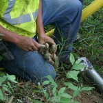
- They loop the end of the gas line around the end pin and tape it to itself along with the #10 electrical tracer wire.
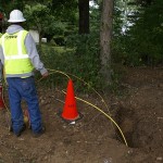
- One worked makes sure the gas line feeds correctly while the crew chief makes sure the tracer wire feeds correctly.
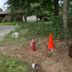
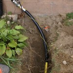
- Our 1″ id branch line where it emerges from underground by the 2″ main line near the street.
- The final piece of gas line with the connector and shutoff valve. Part of the black line will be buried and part will be above ground.
Gallery Four – Hanging The Gas Meter
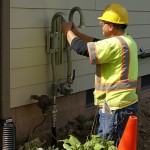
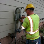
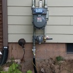
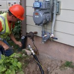
- This guy installed the meter and fused the gas lines. The branch line is connected to the bottom of the left tube near the propane regulator.
- Getting the bracket ready to hang the gas meter.
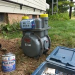
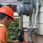
- This is what the workers refered to as a “425” meter. It’s bigger than most residential gas meters, but we have a lot o stuff in the house that uses gas (that’s why we have two propane tanks).
- The gas meter is the large device at the top. It’s purpose is measure the amount of gas we use so Consumer’s Energy can charge us for it. The small round device directly below it is the pressure regulator that drops the pressure from 60 PSI in the branch line to 7 inches of water column (~ 1/4 PSI) in the lines going to the house.
Gallery Five – Fusing The Branch Line to the Main Line And Putting Gas To The House
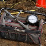
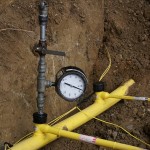
- This is the test fixture they used to pressure test our branch line before finalizing the connection.
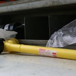
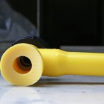
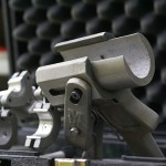
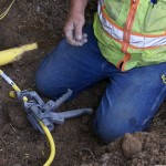
- There are several pictures of this. The long skinny piece to the right gets connected to our branch line. The T on the left gets fused to the main line. Under the black cap is the tap that they use to cut a hole into the main line, allowing gas to flow to the meter.
- One end of the T is curved to exactly match the outside curvature of the 2″ main gas line.
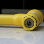
- This hex socket has a tap (cutter) on the other end. When they turn this it drills down into the 2″ main line and creates an opening through which gas can flow to the branch line.
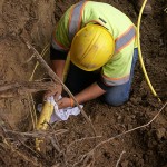
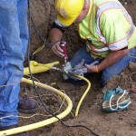
- The main line has been uncovered and the fuser cleans off the spot where he will attach our branch line T-Tap.
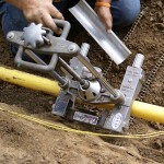
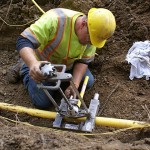
- The base of this jig was secured to the 2″ main line. The metal half-pipe goes on the underside of the main line before the chains are secured.
- The fuser does a test fit of the T-Tap to make sure the jig is adjusted correctly.
- This very specialized heating iron will soften both the 2″ main line and the T-Tap at the same time.
- The heating iron positioned in the jig on top of the main line. The T-Tap has not yet been lowered.
- The T-Tap has been lowerd in contact with the heating iron. Time, temperaure, and pressure all became critical at this point.
- As soon as the heating iron was removed the jig was used to bring the saddle of the T-Tap into contact with the top surface of the main line and then clamp them together with a specified pressure for a long enough time for the plastic to fuse (melt together and then cool).
- This neat little handheld jig was used to hold smaller branch lines and connect them to each other or to the T-Tap outlet.
- This photo shows our branch line connecte (fused) to the end of the T-Tap. The long piece of the T-Tap has a check valve inside to prevent an open gas leak in they event of a problem with our line or meter later on.
- This our neighbor’s branch line being set up for fusing to their T-Tap.
- A different heating iron is used with this branch line jig to soften the ends of the plastic to be fused.
- As before, the heating iron is removed and the ends to be fused are brought together and held until they melt together and then cool.
- The green trailer to the left is a high capacity air compressor to supply air for testing the branch line for leaks before tapping into the main.
- The pressure test fixture attached to the top of our T-Tap with the air compressor line attached to the top of the fixture.
- The 2″ main line carries natural gas at 57 – 60 PSI. They pressure tested our branch line at 92 PSI for 10 minutes.
- Our branch line held the test pressure for the required time, so they moved along to finish the installation.
- For the final hookup they disconected the branch line from the meter, opened the valve, and purged the air from the line until they had nothing but natural gas coming out.
- They reconnected the branch line, opened the valve, and we had gas to our meter. They then checked all of the connections for leaks.
