[ This post contains some narrative but consists mostly of 17 photos with captions. ]
SUNDAY 16 April
I finally started painting inside the barn today. Priming actually, but first I finished masking off areas of the concrete floor where I would be painting, using a combination of red rosin paper and masking tape. Before starting on the interior of the staircase, however, I removed the handrail leading up to the storeroom, removed all of the hardware, and set it across a pair of sawhorses in the driveway. There was rain in the forecast, but initially the weather was okay, with a high temperature forecast of 74 degrees F.
I rubbed down the handrail with 0000 steel wool, and then opened a container of Kills2 primer that I had left from this past fall. I gave it a good stir, and used a tapered trim brush to apply it the bottom and sides. I then moved inside and did all of the “cutting in” in preparation for eventually using rollers for the large surface areas. I used up the remaining Kills2, and opened the new 5-gallon pail.
These pails have a 3” (approx.) screw off cap, and I have screw on spouts that replace them to allow pouring the contents without removing the entire large snap on cover. Not that it’s easy—these pails are heavy when full—but it is much less messy than removing the large lid and then trying to pour the contents. I transferred a small amount of the primer into the old, smaller (~ 3 gallon) pail, and set about the work.
The rain did eventually come, and I had to move the handrail and sawhorses inside along the west shop wall. As mentioned yesterday, Linda and I had already placed red rosin paper ~3’ wide, along the base of the two large walls that are inside the barn but form two of the exterior walls of the shop/storeroom in the NE corner of the building.
MONDAY 17 April
As forecast, a cold front came through yesterday, with high, gusty winds, and the temperature started falling noticeably by mid-afternoon. The overnight low dropped below freezing, and we awoke this morning to snow. In anticipation of this, I had moved all of the primer and paint into the shop portion of the barn yesterday, as it is well insulated and had warmed up nicely with the very warm weather of recent days. The forecast was for three nights below freezing, but not by much, with highs above freezing, so I figured the paint should be okay. Overnight lows in the 30’s were forecast again for four nights starting this coming Saturday, but from tomorrow on the weather should be amenable to the work I need to get done in the barn.
Given the weather forecast, today was a good day to work on blog posts, including the processing of photos. I shot over 1,500 frames on our 15-night/16-day Panama Canal cruise, around 500 of them just on the day we did the transit of the Canal. It takes a lot of time to go through that many images, select the ones I want to use (that support the narrative or tell a story in their own right), and post-process them. It also takes a lot of time to craft the narrative, especially more than a month after the events.
TUESDAY 18 & WEDNESDAY 19 April
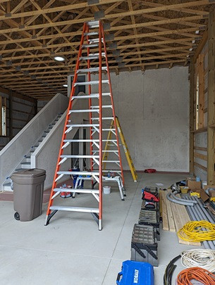
A view of the East (small RV) bay with equipment and supplies. The wall behind the step-ladder and the walls of the staircase have been painted and primed. Not yet done, and saved for later, is painting all of the staircase trim in a contrasting color, probably a green to match the lower exterior siding,
I managed to complete all of the cutting-in except for the a few spots high up at the exterior barn walls, as I need the 14’ stepladder to reach these, and I need someone to help me move it. Linda was working on accounting for the bakery, and did not need to be interrupted. The handrail dried, so I was able to turn in right-side-up and finish the first coat of primer.
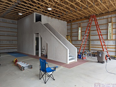
This is another view of the painted walls and staircase as seen from the SW corner the West (large RV) bay looking NE.
THURSDAY 20 – SUNDAY 30 April
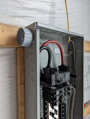
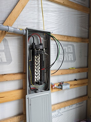
The box adapter has been installed in the upper left corner of the main panel. The inside of the outer portion is smooth to accept the conduit tube. The inner portion is threaded, and retained by a conduit lock-nut. Note that in any photos of the main panel with the cover removed, the main breaker/disconnect is OPEN, so the bus bars are NOT energized. The very large black and red cables at the top, however, are energized but the terminating lugs have safety covers. Still, this is no place to get careless. I am always extremely mindful of the location of these “live” terminals.
During this time period we installed the 2” Sch 40 PVC conduit from the main panel to the sub-panel in the shop, and ran the feeder wires. It might not sound like much, but it was our first attempt at installing the conduit. It was a lot of work, and we took out time to figure things out as we went. Here are some highlights of that work in photos with captions.
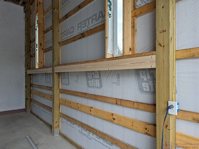
Starting from the post at the right of the frame, we installed a 1×6 board horizontally to the 2×6 boards that are on the flat just underneath the windows. The 2×6 boards support the vertical framing for the windows and extend back for two more posts.
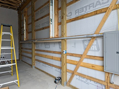
This is almost the same photo as the previous one, except that some of the 2” Sch 40 PVC conduit has been mounted to the 1×6 boards and tied into the main panel box adapter. There is a gap in the conduit about mid-run. An expansion coupling will eventually be installed there.
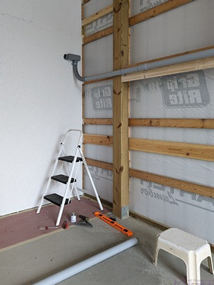
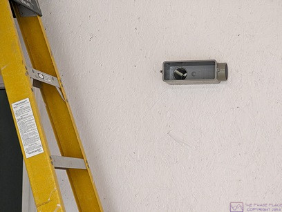
A 90-degree bend (elbow, sweep) has been used to turn the 2” Sch 40 PVC conduit up onto the wall of the shop and terminate it in a 2” PVC LL conduit body at the correct distance from the floor.
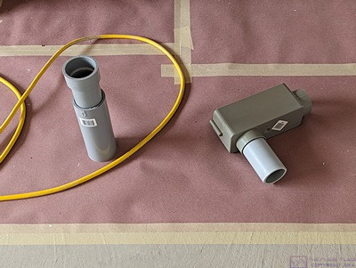
On the left is an expansion joint and on the right is an LB conduit body with a short piece of 2” conduit coming out of the back connection. Two expansion joints were used for this run, one in the middle of the tube from the main panel to the shop wall and the other in the middle of the tube on the shop wall. The stub in the LB conduit body will go through a hole in the wall and connect to another LB conduit body just above the top of the sub-panel in the shop.
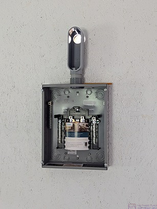
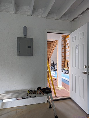
Another 2” PVC LB conduit body inside the shop above the sub-panel. Light is coming through the connection on the back of the LB. A short piece of 2” conduit connects the LB body to a box adapter in the top of the sub-panel. The box adapter is secured from inside the sub-panel with a conduit lock-nut.
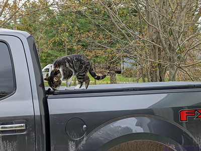
Time out for a cat photo! On this particular day, Cabela decided to visit the barn while we were working and hang out on the bed cover of the F-150. She was exploring at this point, but spent most of her time lying down and sleeping.
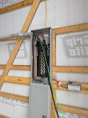
We fed a “fish tape” from the LL conduit body back into the main panel, being careful of the “live” terminals at the top of the enclosure. We had already unwound and straightened the stranded copper feeder conductors—three #4 AWG (red, black, white) and one #6 AWG (green)—and laid them out in the driveway parallel to one another. We attached all four wires to the end of the fish tape. Linda pulled them into the 2” Sch 40 PVC conduit while I fed them in from the main panel. Not shown is that when the wires emerged in the LL conduit body, we: 1) disconnected them from the fish tape, 2) fed the tape from the LB conduit body on the outside of the shop wall back to the LL conduit body, 3) reattached the wires to the end of the fish tape, 4) pulled the wires through the 2” conduit to the LB conduit body while guiding them in from the LL conduit body, and 5) detached them from the fish tape when they emerged form the LB conduit body. This sequence of events would get repeated quite a few times before all of the wires were installed.
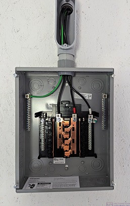
The feeder cables terminated in the shop sub-panel, from left to right: Equipment Grounding Conductor (EGC, Green), L1 (Black), L2 (Red), and Neutral (White). All of the conductors have black insulation except for the EGC. The L2 and Neutral conductors are color coded with tape near the lug connector ends. Note that there is NO connection between the equipment grounding bus and the neutral bus in the sub-panel. Neutral and Ground can only be bonded at one place in the system, and that is at the first disconnect, which in our barn is the main panel. Note also that there is no main circuit breaker in the sub-panel. The L1 and L2 feeder circuit conductors are protected by a 100 Amp, double-pole circuit breaker in the main panel. This circuit breaker also serves as the disconnect for the sub-panel in the even that it needs to be opened and worked on. Until we have final approval of the electrical installation, this circuit breaker has a lock-out device on it to prevent it from being accidentally closed and energizing the sub-panel.
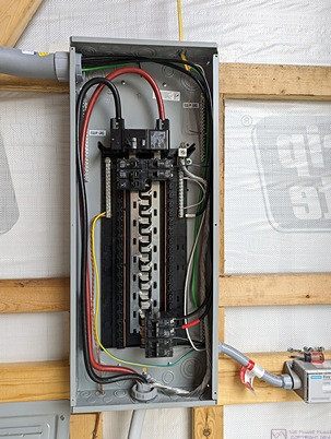
The L2 (Red) and L1 (Black) shop feeder conductors have been “landed” on a double-pole, 50 Amp circuit breaker (3rd and 4th from the bottom in the lower right of the panel). The Neutral (White) feeder conductor has been terminated at the bottom of the neutral bus bar on the right side of the panel, approximate mid-way between the top and bottom of the enclosure. The EGC (Green) has also been terminated in the ground bus, but is under other wires and not really visible.
As of April 29th, the conduit and conductors for the shop feeder circuit were installed and I could finally move ahead with the rest of the conduit and wiring. I decided that the best/easiest thing to do next was the shop and storeroom as I could do most of the work by myself standing on the floor or a short ladder.
…
